Curve Patch
An interactive surface modeling tool for creating surface patches from splines, polygon boundaries, or a combination of both. Supports four-sided patching, single-rail and two-rail sweeps, real-time previews, segment and curvature adjustments, and interactive cutting and segment editing.
User Guide
1. Basic Workflow
① Activate the Tool
Click the Curve Patch icon to display its settings in the Attribute Manager and enter interactive surface patching in the viewport.
Choose Four-Sided Patch, Single-Rail Sweep, Two-Rail Sweep, or Loft under Patch Mode.
② Pick Splines or Polygon Boundaries
Click a spline in the viewport to add it to the current patch inputs.
To pick a polygon boundary, drag from one vertex to another. The plugin finds an edge path along the existing mesh.
Alternatively, select the required edges in polygon Edge mode, then use Convert Current Selection to Boundary in the context menu.
③ Check the Preview
Once the inputs meet the requirements of the current mode, a cyan surface preview and white wireframe appear in the viewport.
Picked boundaries are displayed in different colors. The number beside each boundary shows its current segment count.
④ Adjust the Result
Drag boundaries, enter segment counts, or adjust Curvature, Seed, and Patch Rotation to refine the surface shape and topology.
To add local structure, enter cutting mode and subdivide the region further.
⑤ Apply the Surface
Press Enter, or click Apply at the bottom of the Attribute Manager to generate the final polygon surface.
If no writable polygon object is selected, the plugin creates a new polygon object. If a target polygon object is selected, the generated polygons are added to it.
2. Viewport Interaction and Segment Control
1. Picking Boundaries
Spline boundaries: Click a spline to use it as an input boundary.
Polygon boundaries: Drag from the starting vertex to the ending vertex to pick an edge path along the existing mesh.
If you release the mouse before completing a polygon path, hold Shift to continue picking connected sections. The path must be continuous; disconnected sections cannot be merged directly into one boundary.
2. Highlighting and Multiple Selection
Hover over a colored boundary or its segment number to highlight the corresponding boundary.
Hold Shift and click to select multiple boundaries. Selected boundaries appear white. You can then adjust their segment counts together or use context-menu commands such as Equalize Segment Counts and Group Boundaries.
3. Dragging to Adjust Segments
Place the pointer over an editable boundary or its segment number, then drag left or right with the left mouse button to decrease or increase the segment count.
Original polygon edge paths have fixed topology. Their segment counts cannot be freely adjusted like spline boundaries.
4. Entering an Exact Segment Count
Double-click the number beside a boundary and enter the new segment count.
Enter: Confirm the entry.
Esc: Cancel the entry.
If boundaries are grouped, changing one boundary adjusts the other editable members by the same amount.
For example, if two boundaries have 10 and 20 segments, changing the first to 15 adds 5 segments to the other, giving it 25.
5. Opposite Boundaries in Four-Sided Regions
When a valid four-sided region is first formed, the plugin matches the segment counts of opposite boundaries and links them automatically. Further cuts that create new four-sided regions trigger matching again.
To adjust editable boundaries independently afterward, ungroup them from the context menu.
If one opposite boundary is a fixed polygon edge path and the other is a spline, the spline must match the fixed polygon segment count and cannot be freely adjusted.
Opposite boundaries that both come from fixed polygon paths are also excluded from free segment adjustment.
3. Keyboard Shortcuts
Shortcut |
Function |
|---|---|
Enter |
Apply the current preview; confirm the entry first when editing a number |
Esc |
Cancel numeric input, an unfinished cut, or the current patch inputs |
+ / - |
Increase or decrease segment counts on editable boundaries |
R |
Cycle Patch Rotation |
S |
Toggle between Curvature 0 and the last nonzero adjustment |
Hold K |
Temporarily enter cutting mode |
Shift + Click |
Select multiple boundaries |
Shift + Draw Cut |
Constrain common 45° directions |
Ctrl + Click an Open Spline |
Attempt to cut along the spline in Curve Cut mode |
Scope of Segment Adjustment:
A hovered boundary or segment number takes priority. If multiple boundaries are selected, those boundaries are adjusted.
If no boundary is hovered or selected, all editable spline boundaries are adjusted. Grouped members follow their existing links.
Esc Behavior:
While editing a number, Esc cancels the entry. While drawing a cut, it cancels the current cut path. If no local edit is active, it clears the patch inputs and resets the tool.
Temporary Cutting:
Release K to exit temporary cutting mode. Completed cuts are retained; unfinished cut paths are canceled.
Note: Ctrl-click spline cutting is available only in Curve Cut mode, not Sketch Cut mode.
Attribute Manager
1. General Settings
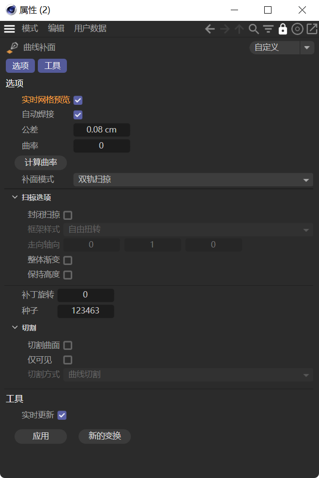
Real-Time Mesh Preview
Controls the display of the cyan surface preview and white wireframe.
When enabled, changes to segment counts, Curvature, Seed, and other settings are visible in the preview.
When disabled, the surface and wireframe are hidden. Picked colored boundaries remain, and the current inputs are not deleted.
Auto Weld
Merges coincident or closely spaced vertices in the generated result.
Primarily used for shared boundaries between adjacent patches, start/end seams in closed sweeps, and matching positions between the generated surface and a target polygon object.
When disabled, some vertices may appear coincident but remain separate.
Auto Weld does not modify the control points of the original splines.
Tolerance
Defines how close two positions must be to be treated as the same location.
Affects endpoint connections, automatic welding, cut endpoint matching, and correspondence between spline and polygon boundaries.
If boundaries appear connected but no preview is generated, first check that their endpoints are close in 3D space, then increase Tolerance slightly if needed.
Excessive tolerance may connect positions that should remain separate. Start with a small value.
Curvature
Adjusts the interior curvature relative to the default surface.
0: Keeps the default calculated surface without adding a curvature adjustment.
Positive values: Add an outward bulge relative to the default surface.
Negative values: Add an inward depression relative to the default surface.
0 does not mean flat, and the first negative step no longer flattens the surface.
Curvature mainly changes the interior shape while leaving the outer input boundaries unchanged. Start with a small value, observe the direction, and adjust gradually.
Press S to toggle between the default surface and the last nonzero adjustment.
Calculate Curvature
Re-estimates the default surface transition using available polygon support surfaces near the boundaries.
Polygon and mixed spline/polygon inputs can use the existing mesh as a reference. Spline-only inputs have no polygon support information and do not use this default curvature fitting.
If the current inputs already use the same calculated result, clicking again may produce no visible change.
Curvature calculation is an approximate fit intended to improve visual transitions. It does not guarantee strict curvature continuity; complex seams may still require manual point, edge, or polygon editing.
Patch Rotation
Changes the starting correspondence and edge-flow direction between the internal topology and input boundaries.
Does not rotate the original splines or model.
If the surface shape is suitable but the internal edge flow is not, adjust this setting or press R to try other orientations.
Seed
Selects from the internal topology solutions available for the current inputs.
Different solutions may change the central structure, pole locations, and edge flow.
The number of solutions is limited by the input boundaries and segment conditions, so different seeds do not always produce different results. Generally, start with the default seed and try other values only when the default solution is unsuitable. After completing the current region, restore the default value to avoid affecting topology generation in subsequent regions.
2. Patch Modes
1. Four-Sided Patch
Fills a valid closed boundary region. Suitable for closing holes, creating surface transitions, and building surfaces from splines.
Despite its name, Four-Sided Patch supports valid closed regions made up of 1–6 boundaries.
Boundaries do not need to be picked in perimeter order, provided they form a valid closed loop.
Steps:
Choose Four-Sided Patch.
Pick the spline or polygon boundaries forming the closed region.
Adjust the segment counts and check the preview.
Adjust Seed, Patch Rotation, and Curvature as needed.
-
Apply to generate the surface.
Multiple Adjacent Regions:
After one region has a preview, continue picking neighboring boundaries. The plugin attempts to identify additional local loops and generate multiple adjacent patches in the same operation.
A boundary shared by adjacent regions usually needs to be picked only once.
2. Two-Rail Sweep
Creates a surface using two rails and one or more cross-sections.
Picking Order:
First rail.
Second rail.
First cross-section.
Continue picking additional cross-sections in order.
The first two curves are treated as rails; subsequent curves are treated as cross-sections.
With one cross-section, it is carried along the full rails. With multiple cross-sections, the surface transitions from the first to the last. On closed rails, Closed Sweep can connect the remaining interval.
Cross-sections may touch the rails or sit between or near them. The plugin establishes correspondence while preserving relative shape and offset.
Suitable for surfaces whose width varies between two rails, ribbon-like structures, and shapes with gradually converging rails.
Note: Ordinary cross-sections in the same set must be either all open or all closed. Do not mix them.
3. Single-Rail Sweep
Creates a surface using one rail and one or more cross-sections.
Picking Order:
Rail.
First cross-section.
Continue picking additional cross-sections in order.
The first curve is treated as the rail; subsequent curves are treated as cross-sections.
With one cross-section, it is carried along the full rail. With multiple cross-sections, the shape transitions in picking order.
Cross-sections may touch the rail or remain offset from it. The plugin establishes correspondence and preserves the offset.
Suitable for tubes, extruded profiles, roads, and surfaces that vary along a spatial curve.
4. Loft
Connects two or more cross-section profiles in order.
Steps:
Choose Loft.
Pick cross-sections in the order you want the surface to pass through them.
Adjust cross-section segment counts and interpolation.
Check the shape and apply.
Picking order is preserved. Cross-sections are not automatically sorted by height or spatial position.
Profiles may be open or closed. Keep their open/closed state consistent within the set and use similar structures and directions where possible.
Two cross-sections transition directly. Three or more can use smooth or linear transitions.
Linear Interpolation
Shown only in Loft mode.
Off: Use smooth transitions between three or more cross-sections.
-
On: Use a linear transition between each adjacent pair of cross-sections.
3. Sweep Options
Closed Sweep
Controls the connection from the last cross-section back to the first on closed rails.
On: Continue along the remaining rail interval after the last cross-section and connect back to the first.
Off: Generate only the interval from the first cross-section to the last.
A single cross-section normally sweeps along the entire closed rail, so toggling this option may make no visible difference.
This option is primarily for closed rails. It does not automatically close an open rail.
Frame Style
Applies only to Single-Rail Sweep. Controls the orientation of cross-sections as they travel along the rail.
Free Twist:
Transports the cross-section orientation continuously along the rail while minimizing sudden flips. Suitable for general planar and spatial curves.
Direction:
Uses a specified fixed up direction. Suitable for roads, stairs, conveyor belts, and structures that require a consistent orientation.
Up Direction
Enabled for Single-Rail Sweep when Frame Style is set to Direction. An XYZ vector defines the reference up direction.
Value |
Reference Direction |
|---|---|
0, 1, 0 |
World Y axis (default) |
1, 0, 0 |
World X axis |
0, 0, 1 |
World Z axis |
An invalid zero vector falls back to the world Y axis.
Global Blend
Controls shape transitions between multiple cross-sections.
Off: Use a separate linear transition between each adjacent pair.
On: Consider surrounding cross-sections for a smoother overall transition.
Requires multiple cross-sections to have an effect. With one there is nothing to blend; with two the result is usually close to linear.
Keep Height
Applies only to Two-Rail Sweep.
When disabled, both cross-section width and height may scale with the distance between the rails.
When enabled, width still follows rail spacing while height is kept as close as possible to its original world-space size.
4. Cutting
Cut Surface
Enables cutting on an existing surface preview.
Cutting requires valid patch inputs and a usable preview. Enabling this option alone does not create a cut when no surface is available.
Enable continuous cutting or hold K to enter cutting mode temporarily.
Visible Only
Controls which depth layers are cut.
On: Cut only the frontmost visible surface layer in the current view.
Off: Cut through overlapping front and back surface regions along the current view.
Choose this option as needed in both perspective and orthographic views. Disable it to cut through the entire preview; enable it to cut only the front region.
Curve Cut
Creates a new cutting boundary on the current surface, dividing the original region into local patches.
Set the start on a valid boundary and the end on another boundary. Add intermediate control positions if needed to adjust the cut path.
Regular Curve Cut attempts to preserve the original parent surface, mainly adding structure and dividing regions.
Cut Along an Existing Spline:
In Curve Cut mode, hold Ctrl and click an existing open spline.
The two spline endpoints must be close to two different boundaries of the same patch region. Once matched, the spline becomes a linked cutting source.
After cutting, adjust the segment counts of the new sections and manage them through the context menu.
Sketch Cut
Searches for available internal topology solutions based on the drawn path, primarily to adjust edge flow.
It differs from Curve Cut and does not guarantee a true, freely shaped cut along the sketch path.
Drawing again in the same location can try other suitable solutions. Results depend on boundary segment counts, region side counts, and shape.
This feature is still being refined. Prefer Curve Cut when you need to divide a region along a specific path.
Context Menu
Hover over a picked boundary or its segment number and right-click to open the menu.
To work with multiple boundaries, first Shift-click to select them. Available commands depend on boundary type, selection count, and the current operation.
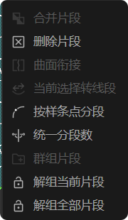
1. Merge Boundaries
Merges connected sections into one input boundary.
Useful when a contour on one side consists of several splines or connected paths that should be treated as a whole.
Selected sections must form a continuous path without gaps or branches.
Only the plugin inputs are merged; original spline objects in the scene are not joined. Segment counts are combined, while fixed polygon sections retain their topology constraints.
2. Delete Boundary
Removes the selected input sections from the plugin without deleting the original spline or polygon objects in the scene.
If the remaining inputs no longer meet generation requirements, the preview disappears. Pick additional valid boundaries to generate it again.
An internal shared cut boundary can also be deleted to merge adjacent regions when the merge conditions are met.
3. Surface Continuity
Adjusts the surface shape near a shared boundary to improve the transition across the seam.
Available for suitable adjacent patches and transitions between a patch and existing polygons.
When existing polygons are involved, you can first select the polygons near the seam that should participate in the adjustment in Polygon mode, then run the command.
This changes the shape near the seam. Check both sides afterward; an ideal transition is not guaranteed for every structure.
4. Convert Current Selection to Boundary
Converts edges already selected in polygon Edge mode into plugin input boundaries.
Selected edges must form a valid open path or closed loop without branches.
Useful for loop boundaries that are difficult to pick by dragging.
5. Segments by Spline Points
Places segments according to the original spline points so those points participate in the topology, rather than distributing segments solely by curve length.
Useful when the edge layout needs to pass through specific spline points or turns.
Segment changes are constrained by the original point layout and may occur in multiples. Unevenly spaced source points can produce uneven segment spacing.
Run the command again to disable it, retain the current segment count, and return to length-based sampling.
Available only for eligible editable spline boundaries. Fixed polygon boundaries and splines constrained by a fixed opposite boundary cannot freely switch this setting.
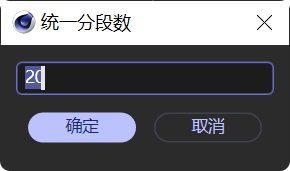
6. Equalize Segment Counts
Sets the selected editable boundaries to the same segment count.
Select the boundaries, run the command, enter the desired count, and confirm.
7. Group Boundaries
Links segment adjustments between two or more boundaries.
Group members do not need to start with equal segment counts. Changing one adjusts the other editable members by the same amount.
For example, group boundaries with 10 and 20 segments. Changing 10 to 15 changes the other count to 25.
To start with equal counts, equalize the segment counts before grouping.
Opposite boundaries in four-sided regions are also linked automatically.
8. Ungroup Current Boundary
Removes the selected section from segment linking. Other members can remain linked.
Useful when only one editable boundary should be adjusted independently.
Ungrouping does not make fixed polygon segment counts freely editable.
9. Ungroup All Boundaries
Removes segment linking from the entire group associated with the selected sections.
All refers to the linked groups of the current selection, not every unrelated group in the scene.
Select members of multiple groups to ungroup those groups together.
Usage Notes
1. A Modeling Aid
A successfully generated surface does not mean the model is finished.
Complex shapes may still require manual vertex adjustment, topology cleanup, curvature refinement, and seam editing. Curve Patch helps establish base surfaces and topology and reduce repetitive work; it cannot solve every modeling problem automatically.
2. Source Splines Determine the Surface Outline
The plugin follows the intermediate-point interpolation of the source splines.
Increasing patch segments mainly adds resolution to the existing shape. It does not automatically turn a polyline into a smooth curve. Refine the spline type, control points, or interpolation settings first.
Splines extracted from industrial models may contain dense points, waviness, or tiny angular steps. Clean them up before generating a surface.
3. Segments Must Match the Inputs
The total boundary segment count in Four-Sided Patch must meet valid topology conditions. An even total is one basic condition, but does not guarantee a solution in every case.
When multiple boundaries use Segments by Spline Points, check that the corresponding point counts and arrangements are compatible.
4. Divide Complex Models into Regions
Too many input boundaries or excessive segment counts increase computation and make results harder to control.
Start with low segment counts to confirm the shape, then increase resolution gradually. Work on complex models in separate regions.
Frequently Asked Questions
1. I Picked Boundaries, but No Preview Appears
Check the following:
Do the Four-Sided Patch boundaries form a true closed loop?
Do endpoints only overlap in the current view while remaining disconnected in 3D space?
Does the local region exceed the supported boundary count?
Do the segment counts satisfy the topology requirements?
Were the sweep rails and cross-sections picked in the correct order?
Is Real-Time Mesh Preview disabled?
Try adjusting editable segment counts or changing Seed. Increase Tolerance only after confirming a small endpoint mismatch.
2. I Cannot Adjust a Boundary’s Segment Count
Polygon edge paths have fixed topology and cannot be freely resampled.
A spline opposite a fixed polygon boundary in a four-sided region must match that fixed segment count and cannot be adjusted independently.
For ordinary grouped boundaries, ungroup them first and then adjust the editable members.
3. The Sweep Twists, Intersects Itself, or Collapses into a Line
Check rail and cross-section picking order, spline direction, cross-section point order, and open/closed state.
For a single rail, try another Frame Style. If a consistent up direction is required, choose Direction and set the appropriate vector.
Large cross-section spans or extreme changes in the rail may also require refining the original inputs.
4. More Segments Do Not Make the Surface Smooth Enough
Check the source spline’s interpolation settings and control-point shape.
Patch segments only add resolution to the existing outline. Refine the spline first if it has sharp turns or waviness.
5. Calculate Curvature Makes No Visible Difference
The current inputs may already use the same default calculated result.
Independent splines without polygon support surfaces cannot use this support-surface fitting.
6. Cutting Does Nothing
First make sure a valid preview exists.
Curve Cut must start and end on valid boundaries. For Ctrl-click spline cutting, the open spline’s endpoints must match two different boundaries of the same region.
Paths with complex reversals, excessive detours, or invalid region divisions may fail. Simplify the path or split the operation into smaller cuts.
7. Context-Menu Commands Are Grayed Out
The command’s requirements have not been met.
For example, merging requires connected sections, grouping requires at least two boundaries, ungrouping requires an existing link, and Segments by Spline Points requires a valid editable spline source.
8. The Generated Surface Still Has Local Issues
Try adjusting Seed, Patch Rotation, segment counts, or Curvature, or split the complex area into smaller regions.
If the base structure is usable, continue refining it with native modeling tools rather than expecting the plugin to finish every detail in one step.
Bug Reports
For a reproducible issue, please provide:
The original scene file.
The plugin version and Cinema 4D version.
The patch mode used.
Complete reproduction steps.
The actual and expected results.
Relevant screenshots or a screen recording.
Keep the original splines, polygons, and settings that trigger the issue so it can be investigated.
Author and Algorithm Credits
Curve Patch is developed by Night Feather; the plugin’s feature design, interactive tools, and integration are the work of its author.
Patch topology generation uses the reference implementation of Pattern-Based Quadrangulation for N-Sided Patches and related helper code.
Paper authors: Kenshi Takayama, Daniele Panozzo, and Olga Sorkine-Hornung, 2014.
Third-party code and libraries belong to their respective copyright holders. Original licenses and copyright notices are included in the plugin’s res/legal directory.
Changelog
- 1.0.0 Curve Patch — Initial Release Generate surfaces from splines, polygon boundaries, or mixed inputs. Includes Four-Sided Patch, Single-Rail Sweep, Two-Rail Sweep, and Loft modes. Interactive viewport controls with real-time mesh preview. Adjustable segment counts, curvature, patch rotation, and topology seed. Surface cutting and boundary editing, including merging, deleting, grouping, and segment linking.